Cockpit panelling

I’d been having sleepless nights thinking about how I’d cover the cockpit…. paint, powdercoat, carpet, adhesive film… The choice was unending and all had their advantages and disadvantages as well as options.

Equally they dictated when and how I fitted panels. If I powder coat and need to trim a panel slightly.. what if I scratch them fitting them. What about the additional thickness. Do I go bare rivets with painted panels (looks IMO awesome but a royal pain to do).

I eventually came to the decision of “fuck it”, I was either going to paint over the lot or cover the lot. I love the look of bare aluminium rivets on black panels but a *lot* of grief and that could go wrong and make it look terrible.

So with that decision made it was on with attaching some panels!

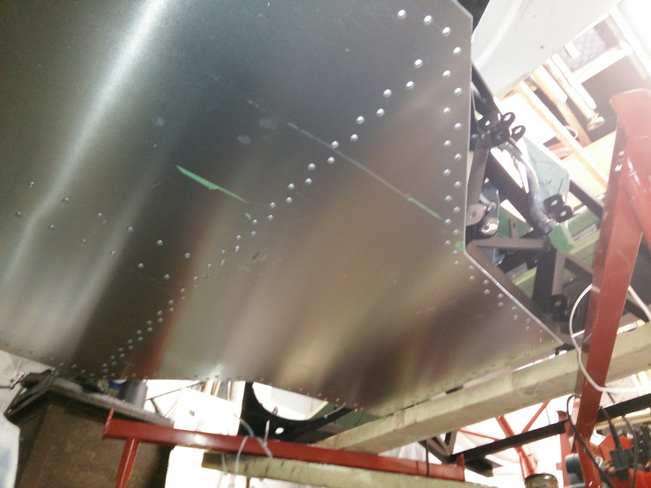
Rear bulkhead panel:

Top not riveted yet as the upper bulkhead “folds over” and overlaps onto the bottom.

Right hand side (with gearchange linkage cover in place):

Note I haven’t cut the hole in the top for the gear lever yet! smiley

Upper row of rivets aren’t yet fitted just because I haven’t yet fitted them, they’re 4.8mm against 4mm for the rest because they’re countersunk and 4.8mm are the smallest countersunk rivets I could find. They’re countersunk because there is a rounded edge trim piece to go over the sharp corner edge there (for IVA etc) and without flush rivets the trim wouldn’t sit flush.

Left hand side:

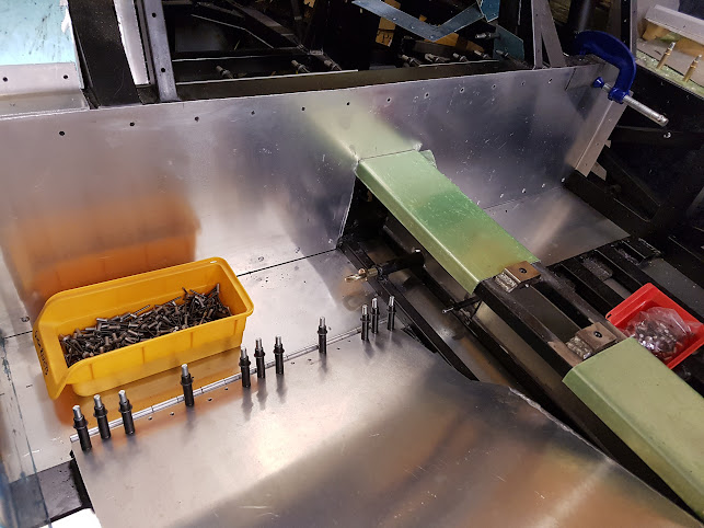
Incidentally I found a *lot* of rivets were “out of spec” and oversize. I ended up “dumping” a whole load as I was fitting them, if they wouldn’t fit I’d throw them and pick another one. You can see how many “unused” ones along with the discarded shanks there are on the floor. I’ll probably still use them but for the holes that ended up a little larger than intended but next time I’ll be checking them for size first as it was a royal pain trying to fit them and having sometimes to try 2 or 3 before they’d fit. Plus all the sealant that got over them.

Anyway, then moved on to the gearchange linkage cover, fitted a piece of right angle at the top to the sill side, drilled the two panels to attach them together and then fitted into place. Drilled the top to the right angle (4mm at the moment, I’ll enlarge and fit riv-nuts later). Then I fitted two pieces of right angle to the floor “behind” the panel (one either side of the seat mounting flat bar) and then one in front so that it is positively located.

I had to cut down the one in front as it slots in at an angle to clear the seatbelt mount.


Reversed A Arms

As with everything I went my own way slightly on the rear suspension…

The “kit” reversed A arms were rubber bushed and didn’t twist in the chassis, this meant that the uprights couldn’t be angled back to provide the correct suspension geometry (I modelled this extensively)… Plus as a bonus the chassis mods meant they clashed now with the chassis.

Yet again making a rod for my own back.

So we started off with the advanced pipe notcher…

And some machined spherical bearing housings.

A bit of welding later…


And into the jig.

Much fettling later and we have a pair of rear arms

Although I did sell out and get someone to make up the adjusters… even though I have a lathe it was cheaper than just buying the metal and the tooling!

Only took me a month and a half to make!

Finally have a comparison between old and new.


Flywheel

I found someone who did a 1UZ-FE to BMW flywheel, as it’s the same diameter as the 01E clutch I was planning to use, with some measurements I figured it should work and save having to make my own.

I obviously need a pressure plate but that should be straightforward.

Now the only question is over the clutch disc. Do I go for sprung (noting obviously that this *actual* clutch plate is dead and I’d need a new one)

Or unsprung (brand new clutch plate but only cost me £10 so I’m not too concerned about throwing it away).

My thoughts are that it should be sprung, on the basis that in the original fitment for the unsprung disc the car was fitted with a DMF which would have been sprung and the RS4/S4 etc are sprung (as well I believe still fitted with a DMF).


Sill beading

So, anyone who’s seen a real GT40 will know the sills look like this.

ie with some lovely beading in and I wanted to replicate that.

The original ribs should be 1.060″ (26.924mm) wide by 0.240″ (6.096mm) high according to http://www.racingicons.com/gt/process.htm

While not quite right (but IMO close enough for a space frame replica!) I noticed you could get a 1″ (25.4mm) wide by 3/16″ (4.7625mm) high half round aluminium strip for a very reasonable price.

A bit of cutting later and I had 4 long and 2 short strips. Then hammer flat the ends

and grind them so they are round.

These will go here

I’ll stick them on the sill tops with some Sikaflex 252 but they’ll look something like this


The Floor

With a space frame like the GT40 replicas the floor is an important structural part so no pissing about with this.

Started with a massive sheet of 2.5mm aluminium. Laid it on the bottom of the chassis and drew round all of the chassis members. Then out again and cut it to shape.

Then mark up and drill ~450 2mm holes. The eagle eyed reader may spot my school boy error at this point.wink

Then clamped back to the bottom of the car and drilled with 4mm into the chassis

Then drilled out to 4.8mm before being removed and stored for a year….

Then protective film off, admire the shiny!

Then absolutely crippled myself attempting to apply Sikaflex 252 using a hand held caulk gun. In hindsight I should have bought an air gun but I just hadn’t realised how hard it would be!

Stuck the floor on and then riveted it in place. ~450 rivets later and it was done.


Rear uprights

The original “kit” came with uprights spec’d for Granada rear hubs, bearings etc. Now I did manage to get hold of some but for a number of reasons ended up selling them on again. The main reason being I decided to use more modern kit. Specifically Audi from a mix of models.

Bearings IIRC were A6 front bearings but also as fitted to the R8

Hubs are A8 but also same as fitted to the Lamborghini Gallardo LP560/LP550 as well as Audi R8…

Seen here in comparison to the Granada ones (that’s an A6 driveshaft and Granada stub shaft btw).

Inner and outer CV’s are S4. Pictured like this to confirm clearance with the mounting bolts

The Audi hubs of course did not line up. It was close but just not close enough.

Bolts are tight on the inside but just about fit

First things first, put some steel into the lathe and make up some spacers. Spacers rather than bore out the upright for one main reason,  because the disk clashes with the upright otherwise. smiley

Then it’s just a case of welding up the original holes, grind it flat again (the inside was a bitch to do).

Then weld on the spacer plate and drill out the holes.


Rear Brakes

Rear brakes are HiSpec Rear SVA Billet Universal Lug (140mm PCD) Calipers

Disks are 312mm x 25mm vented. As fitted to the Audi A6 2.5TDI (for a number of reasons which I will clarify elsewhere).

Handbrake lever

As ever, not totally happy with the original kit design so modified it (I swear I’d have completed this car already if I didn’t keep thinking similar).

Original

Working out where I want it.

And then new mounts welded in.

Each one of those brackets consists of 4 parts… a ridiculous amount of effort! But now the lower pivot of the lever goes no lower than the bottom of the rails that make up the “tunnel”.

Then welded in a piece of steel to mount the cables into.

The handbrake cables which I bought from HiSpec with the calipers will then just slot into these.

The only issue here is that the handbrake is not central and would pull them to one side. I need to think about this some more.


Tanks

The original GT40 had bladder type tanks inside the sills. These are an absolute fortune to buy and need regular replacement. The space frame replicas both don’t have this area and I’m not going to be racing this there is no need so it’s normal tanks.

Myself and a few like-minded GT40 builders decided that the very best way was to get someone to make up a batch of tanks. That way we could just pay fabrication + material costs and get a bulk discount.

A shot while later we each got two tanks, one for each side.


As these are very long they’re baffled inside

plus (although you can’t see it) there is a trap door at the end to try and keep all the fuel running away under braking/descents. There will also be a decent sized swirl pot with lift pumps as well so it should be ok.

The tanks have the obvious fill port, two vents (one each end), one feed and one return. Fittings are all AN.

There was only one issue now. How to mount them. In the end I went for stainless straps, 4 per tank. These are utter overkill. Consisting of 2 parts each with 5 different types. Two front ends, two rear ends (mirrors of each) and the middle straps.

These pivot at the bottom on mounts welded to the frame

At the top they bolt into top hat adaptors which are fitted through the chassis and tacked onto the back.

Fuel sender access

I got a load of 2mm plates cut to the ATL blank 4″x6″ size.

Sold most on ebay which left me with the remaining ones “free”. smiley

These were then attached with countersunk rivnuts to the sills

I added some washers behind the rivnuts as the countersinking left the panels a little bit thin.

I’ve not bothered to cut “through” although the centres are drilled for if I want to.

Bonus points for spotting a school boy error here though. sad


Finally a picture of the sill with them (and fake ribs) in place