Category Archives: Interior

Steering column change #3

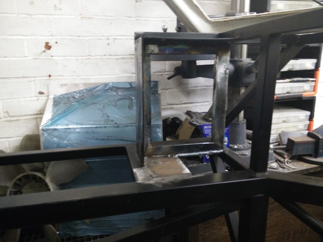
So the test was successful, time to make it permanent.

A little bit of welding later

Testing for fit in the car again.

Next up, weld it in place.

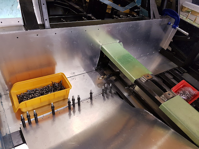
I ended up cutting back the front here as while it “fitted” it was rather too close to the clocks

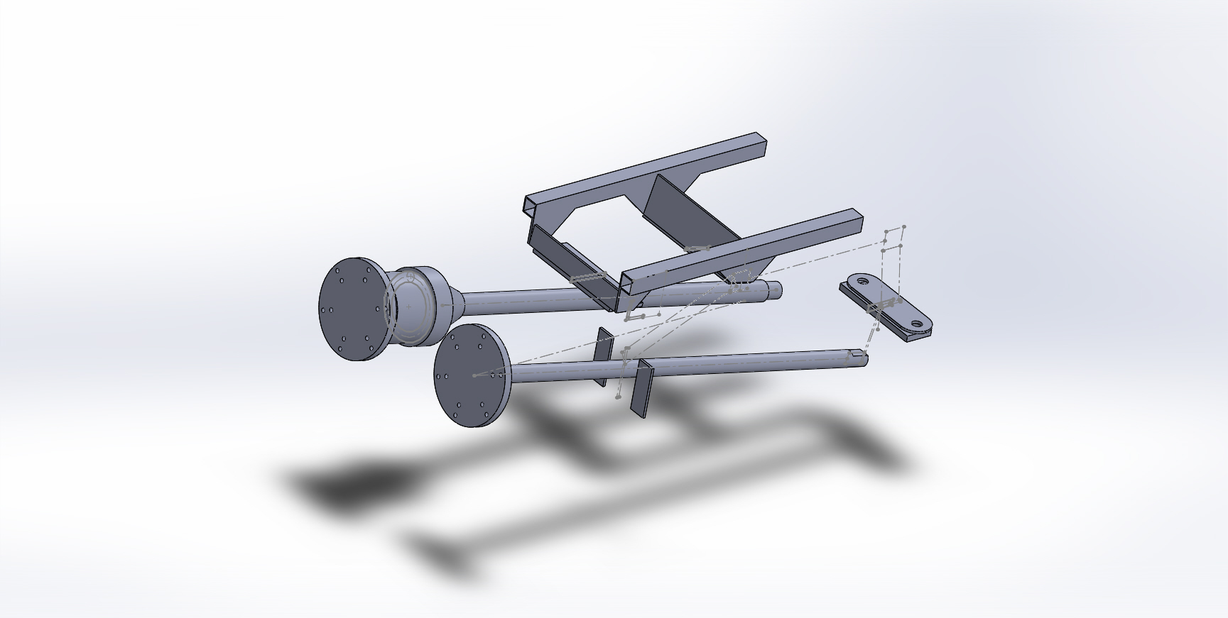
Finally, here you can see the difference in column location. The chassis tube running up/down in this image is the original centre line.

With the column in place behind the dash.

And again.

Finally with the wheel in place.

Note that the steering lock is fully usable still which helps with IVA but unfortunately the stalks don’t fit.

My intention is to use the original wheel with a padded centre replacing the airbag.

I may at a later date replace the wheel with a more appropriate one but this appears to be tricky as while the spline is not unique to the Wagon R/Agila A (it’s shared with the BMW E46) the adaptor for the E46 doesn’t fit particularly well due to the differences in the column hardware.

I’ll worry about that once its passed the IVA!

Steering column change #2

First off I had a play with CAD and drew up the various locations and where to put things. Then I created a model to hold things (taking into consideration the substantial torque put into the chassis by EPAS). Here’s the comparison between the two mounts.

Next I 3D printed a version designed to slide on some bar clamped to the chassis to test things really worked.

Yep, that’s about right.

Clearance is fine underneath.

Next up we need to cut the dash so it’ll fit through.

Before

After

Perfect fit.

No really, perfect fit.


Steering column change #1

For various reasons I decided to swap the original dash I had for a Lee Dawson one. At the time I picked it up he commented that someone else had said it didn’t fit the Forte (but he’d buy it back if that was the case as “he can sell them all day”).

Anyway, I tried it and it doesn’t fit. I measured things and had a revelation. The original  GTs40 dash is larger, has the steering column in a different place and has hence been reprofiled, that’s *why* it’s distorted as it’s not quite worked.

If you take the centre of the seat to be the “ideal” position then the original was offset ~31mm to the left while the LD would make that ~14.5mm

The new dash is 44mm narrower. If centralised the difference between the column positions was 45.5mm which accounting for the difficulty in measuring makes it near as dammit the difference in size between the two dashboards.

After a bit of a think about things I broke out the angle grinder.

This then let me fit the dash

I then messed about with relocating the steering column only to run into a major issue. It doesn’t fit.  The column has to move over about 50mm but the most it can move before the motor hits the side of the chassis is 30mm.

Back to the drawing board. Either a manual column or a different power steering column.

Step forwards please the Suzuki Wagon R / Vauxhall Agila A powered column. This is both 30mm narrower and the motor points up not down. Due to the way the panel slopes out at the top this increases the room available.

As a bonus it’s both lighter and has an electronic clutch. This means that assistance is optional and when not powered is only very slightly heavier than a fully manual column.

As a size comparison

Roughly clamped in place

VS the Corsa B column

That should work then. Now I just had to attach it securely.


Fuel filler close off panelling

The IVA requirements state that no part of the fuel system can be in the passenger compartment and the fuel tanks must be the other side of a (sealed) bulkhead.  In the GT40 the fuel fillers are on the scuttle just front of the A pillars and the filler hoses pass down in those front corners to the tanks.

This in my chassis is open and needs closing off.

Now many years back I had a consideration of that area and considered it somewhat lacking. The roll cage (which as I’m sure I’ve mentioned previously) I’d already decided not to fit on the road *but* if I did fit it then it sat on a simple unbraced flange.

A big off landing on the roof I could see just folding that plate.

So after some contemplation I welded in a flange all the way round, as well as closing off the front bit.

I also welded a piece over half of the “hole” to the tank area and put in a weld nut to earth the tanks to (the tanks also have a welded on “nut” to attach a strap to), that’s what the bolt sticking up is in, I put it in when I painted it to keep paint out of the threads to give good connectivity.

Here is it from the other side (and also the other side).

This also means that an access hatch can easily be created and bolted on

So anyway, way back in 2015 I made the closer panel for the right side.

I wasn’t totally happy with it, due to the design of the panel it made the folds awkward, I couldn’t use the sheet folder because of the multiple flanges and partly for that reason I put off the left side. Cracking on with getting stuff done however so I had a big think about the left and decided to do it in three pieces. This makes it trickier to seal (although everything is being sealed with both PU adhesive/sealer as well as aluminium tape) but much easier to make.

If I was to do it again from scratch I would extend the plate I welded in underneath, leave a flange on it and add a plate to the top (with a flange) so that the closer plate simply became a two fold affair.

Tunnel vision

Another one that has been years in progress. smiley

The GT40 as a mid-engined car runs the water pipes front to back, these run through the “tunnel” in the middle of the car… along with everything else!

Now as everything there are trade offs with sizes but settled on 1.5in (OD) tubing but this is a bit of a squeeze. The limits of the tunnel are hard, defined by the “box” section in the chassis.


The biggest issue really being in the air-con lines. Everything fits but with normal barrier air-con hose things are *very* tight.

I really need to find either reduced diameter barrier hose *or* run hard-lines. I’m struggling to find anywhere that will make me some up in the UK (I’ve found plenty of places in Aus and the US, especially Florida for some reasons wink )

Anyway, I decided I would cross that bridge when I came to it and cracked on with things. First off was to consider the sides, these were pretty easy. A simple “side”

Then with a folded piece on top.

Then as foot room was tight I wanted as much as possible… Seeing as the first ~20mm of the “tunnel” would be wasted space I put the front end of the tunnel to the left as much as possible, running flush against the inside of the hard limit.

Still not a lot of room!

The other side, I made with a dividing wall, the wiring, clutch and brakes will run down this in an attempt to keep them cool and also to allow access. There is no “access” to the rest of the pipework, it could be replaced but would be slid through.

That was way back in 2015. With the floor installed I could finish it off.

First issue was that I’d raised the handbrake up. So I cut down the top section, I still need a new bit for the front (it looks like it’s sorted here but the bit at the front is too short) as well as the sides. but the back half is sorted.

Then it was onto attaching it to the floor as well as sorting the bulkhead end. Long story short, here it is.

There are a *lot* of clecos hidden in here!

Cockpit panelling

I’d been having sleepless nights thinking about how I’d cover the cockpit…. paint, powdercoat, carpet, adhesive film… The choice was unending and all had their advantages and disadvantages as well as options.

Equally they dictated when and how I fitted panels. If I powder coat and need to trim a panel slightly.. what if I scratch them fitting them. What about the additional thickness. Do I go bare rivets with painted panels (looks IMO awesome but a royal pain to do).

I eventually came to the decision of “fuck it”, I was either going to paint over the lot or cover the lot. I love the look of bare aluminium rivets on black panels but a *lot* of grief and that could go wrong and make it look terrible.

So with that decision made it was on with attaching some panels!

Rear bulkhead panel:

Top not riveted yet as the upper bulkhead “folds over” and overlaps onto the bottom.

Right hand side (with gearchange linkage cover in place):

Note I haven’t cut the hole in the top for the gear lever yet! smiley

Upper row of rivets aren’t yet fitted just because I haven’t yet fitted them, they’re 4.8mm against 4mm for the rest because they’re countersunk and 4.8mm are the smallest countersunk rivets I could find. They’re countersunk because there is a rounded edge trim piece to go over the sharp corner edge there (for IVA etc) and without flush rivets the trim wouldn’t sit flush.

Left hand side:

Incidentally I found a *lot* of rivets were “out of spec” and oversize. I ended up “dumping” a whole load as I was fitting them, if they wouldn’t fit I’d throw them and pick another one. You can see how many “unused” ones along with the discarded shanks there are on the floor. I’ll probably still use them but for the holes that ended up a little larger than intended but next time I’ll be checking them for size first as it was a royal pain trying to fit them and having sometimes to try 2 or 3 before they’d fit. Plus all the sealant that got over them.

Anyway, then moved on to the gearchange linkage cover, fitted a piece of right angle at the top to the sill side, drilled the two panels to attach them together and then fitted into place. Drilled the top to the right angle (4mm at the moment, I’ll enlarge and fit riv-nuts later). Then I fitted two pieces of right angle to the floor “behind” the panel (one either side of the seat mounting flat bar) and then one in front so that it is positively located.

I had to cut down the one in front as it slots in at an angle to clear the seatbelt mount.


Sill beading

So, anyone who’s seen a real GT40 will know the sills look like this.

ie with some lovely beading in and I wanted to replicate that.

The original ribs should be 1.060″ (26.924mm) wide by 0.240″ (6.096mm) high according to http://www.racingicons.com/gt/process.htm

While not quite right (but IMO close enough for a space frame replica!) I noticed you could get a 1″ (25.4mm) wide by 3/16″ (4.7625mm) high half round aluminium strip for a very reasonable price.

A bit of cutting later and I had 4 long and 2 short strips. Then hammer flat the ends

and grind them so they are round.

These will go here

I’ll stick them on the sill tops with some Sikaflex 252 but they’ll look something like this


Fuel sender access

I got a load of 2mm plates cut to the ATL blank 4″x6″ size.

Sold most on ebay which left me with the remaining ones “free”. smiley

These were then attached with countersunk rivnuts to the sills

I added some washers behind the rivnuts as the countersinking left the panels a little bit thin.

I’ve not bothered to cut “through” although the centres are drilled for if I want to.

Bonus points for spotting a school boy error here though. sad


Finally a picture of the sill with them (and fake ribs) in place

Roll cage delete

My kit came with a roll cage. After a lot of thought however I decided to remove it.

A roll cage is a good thing in a GT40 as the A pillars are almost non-existent. I’ve heard tales of GT40-inexperienced passengers cracking the screen by using the A pillar to grab on to.

There is a big but here. Only if you are religious about wearing a helmet. Even a minor bump without one could result in “life changing” head injuries. There is next to no clearance in the GT40 and I personally felt the risk of hitting the roll cage in a minor bump was higher than the roll cage saving you (on the road).

There was only one issue however. I’m likely to want a cage in at some point if (when) I take it on track which is some what of an issue as even with the roll cage “removed” the stubs on the roll-over bar remain and are pretty much just as bad.

Plus it’s actually impossible to fit the roll cage without removing the spider and (almost certainly) impossible to remove the spider without breaking the windscreen.

A lot of thought later and I had a solution. First I cut off the stubs.

Then I took two identical strips, drilled 8 holes through both and welded in weld nuts to the back.

This was then welded onto the roll-over bar part of the roll cage to give this

The rear bulkhead was then trimmed round it. Now it protrudes but only very slightly.

With the window cut out it looks like this

I’ll put a bit of a cover over it however to blend it in more.

This will let me bolt in a cage if I want (I’ll have to be two part still) without removing the spider and without leaving the dangerous stubs.


Gearchange part 2 (the mechanism)

So, with the gearlever in place it was time to think about how things would get from the lever to the gearbox. A bit of a play with some bar seemed to indicate a rod shift was just possible.

Albeit mightily tight

So I made up a bracket with a bush and welded it to the chassis

Now, I just needed to work out how to get it the rod here (the pointy ended one) link through to the other side of the gearbox.

That can wait until the gearbox is back in however.