Monthly Archives: September 2017

Aircon / Heating part 2

A few years back I fitted the Nostalgic AC aircon / heater but there was a problem.

The mountings are on sliding nuts and there is virtually no clearance on the left of the car… Once it was in that would be it, no removal short of removing multiple panels from the car which would involve drilling out lots of rivets as well as removing the panels from the sealant.

So it got shelved for a while while I mulled over the problem. Eventually I thought up of a solution. I could open up the holes and use rubber grommets with “studs” on the left instead of bolts. I opened up the holes and then hit another snag. The grommets didn’t fit as the mounting plates were 3mm and the grommets are designed for panel work, ie ~1-1.5mm.

I thought of a solution but didn’t have the materials so I shelved it again while I cracked on with other stuff.  Eventually I got round to it as I needed to buy the material for another part of the car.

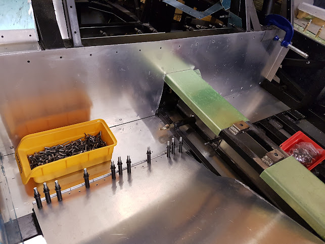
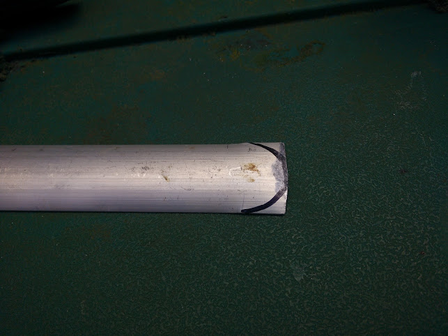
The solution, delrin. I made up 4 “top hats” out of delrin, these fit into the holes as such.

These are bolted onto the AC unit like so

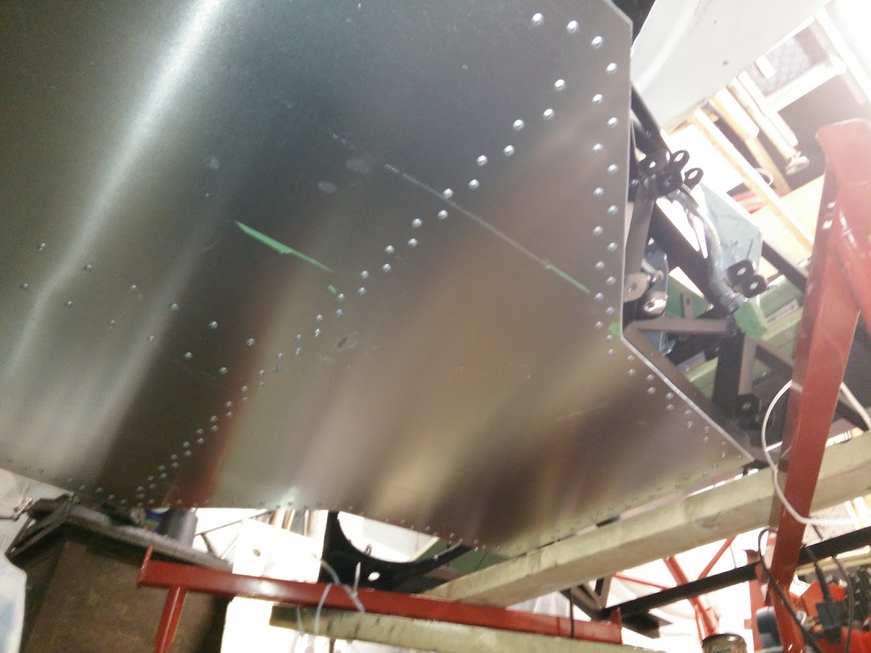
They’ll just slot in to the left hand side and the right will bolt up as normal. Access has been granted via suitable access panels cut in above.


More panelling

So now ready to crack on with panelling in earnest.

Next on the sill outer sides. I suspect I’m rare in bothering to panel this area but there are good reasons, first one is that with bonding and (lots of) rivets the panels become structural and the sills form a large portion of the stiffness in the chassis. The second one is because in the GT40 the fuel tanks sit in the sills. The panels both increase the separation but also will be (fire proof) foam filled to give additional time should the worst happen.

Anyway, before.

After

Then with that in place it was onto the panelling at the front, lots of sections have prerequisite panels and a defined order to assemble. The front is probably the worst for this. I don’t appear to have a recent photo here so I’ll have to go right back to the start of the project (my god look how empty and clean the garage was!)

After


Fuel filler close off panelling

The IVA requirements state that no part of the fuel system can be in the passenger compartment and the fuel tanks must be the other side of a (sealed) bulkhead.  In the GT40 the fuel fillers are on the scuttle just front of the A pillars and the filler hoses pass down in those front corners to the tanks.

This in my chassis is open and needs closing off.

Now many years back I had a consideration of that area and considered it somewhat lacking. The roll cage (which as I’m sure I’ve mentioned previously) I’d already decided not to fit on the road *but* if I did fit it then it sat on a simple unbraced flange.

A big off landing on the roof I could see just folding that plate.

So after some contemplation I welded in a flange all the way round, as well as closing off the front bit.

I also welded a piece over half of the “hole” to the tank area and put in a weld nut to earth the tanks to (the tanks also have a welded on “nut” to attach a strap to), that’s what the bolt sticking up is in, I put it in when I painted it to keep paint out of the threads to give good connectivity.

Here is it from the other side (and also the other side).

This also means that an access hatch can easily be created and bolted on

So anyway, way back in 2015 I made the closer panel for the right side.

I wasn’t totally happy with it, due to the design of the panel it made the folds awkward, I couldn’t use the sheet folder because of the multiple flanges and partly for that reason I put off the left side. Cracking on with getting stuff done however so I had a big think about the left and decided to do it in three pieces. This makes it trickier to seal (although everything is being sealed with both PU adhesive/sealer as well as aluminium tape) but much easier to make.

If I was to do it again from scratch I would extend the plate I welded in underneath, leave a flange on it and add a plate to the top (with a flange) so that the closer plate simply became a two fold affair.

Tunnel vision

Another one that has been years in progress. smiley

The GT40 as a mid-engined car runs the water pipes front to back, these run through the “tunnel” in the middle of the car… along with everything else!

Now as everything there are trade offs with sizes but settled on 1.5in (OD) tubing but this is a bit of a squeeze. The limits of the tunnel are hard, defined by the “box” section in the chassis.


The biggest issue really being in the air-con lines. Everything fits but with normal barrier air-con hose things are *very* tight.

I really need to find either reduced diameter barrier hose *or* run hard-lines. I’m struggling to find anywhere that will make me some up in the UK (I’ve found plenty of places in Aus and the US, especially Florida for some reasons wink )

Anyway, I decided I would cross that bridge when I came to it and cracked on with things. First off was to consider the sides, these were pretty easy. A simple “side”

Then with a folded piece on top.

Then as foot room was tight I wanted as much as possible… Seeing as the first ~20mm of the “tunnel” would be wasted space I put the front end of the tunnel to the left as much as possible, running flush against the inside of the hard limit.

Still not a lot of room!

The other side, I made with a dividing wall, the wiring, clutch and brakes will run down this in an attempt to keep them cool and also to allow access. There is no “access” to the rest of the pipework, it could be replaced but would be slid through.

That was way back in 2015. With the floor installed I could finish it off.

First issue was that I’d raised the handbrake up. So I cut down the top section, I still need a new bit for the front (it looks like it’s sorted here but the bit at the front is too short) as well as the sides. but the back half is sorted.

Then it was onto attaching it to the floor as well as sorting the bulkhead end. Long story short, here it is.

There are a *lot* of clecos hidden in here!

Cockpit panelling

I’d been having sleepless nights thinking about how I’d cover the cockpit…. paint, powdercoat, carpet, adhesive film… The choice was unending and all had their advantages and disadvantages as well as options.

Equally they dictated when and how I fitted panels. If I powder coat and need to trim a panel slightly.. what if I scratch them fitting them. What about the additional thickness. Do I go bare rivets with painted panels (looks IMO awesome but a royal pain to do).

I eventually came to the decision of “fuck it”, I was either going to paint over the lot or cover the lot. I love the look of bare aluminium rivets on black panels but a *lot* of grief and that could go wrong and make it look terrible.

So with that decision made it was on with attaching some panels!

Rear bulkhead panel:

Top not riveted yet as the upper bulkhead “folds over” and overlaps onto the bottom.

Right hand side (with gearchange linkage cover in place):

Note I haven’t cut the hole in the top for the gear lever yet! smiley

Upper row of rivets aren’t yet fitted just because I haven’t yet fitted them, they’re 4.8mm against 4mm for the rest because they’re countersunk and 4.8mm are the smallest countersunk rivets I could find. They’re countersunk because there is a rounded edge trim piece to go over the sharp corner edge there (for IVA etc) and without flush rivets the trim wouldn’t sit flush.

Left hand side:

Incidentally I found a *lot* of rivets were “out of spec” and oversize. I ended up “dumping” a whole load as I was fitting them, if they wouldn’t fit I’d throw them and pick another one. You can see how many “unused” ones along with the discarded shanks there are on the floor. I’ll probably still use them but for the holes that ended up a little larger than intended but next time I’ll be checking them for size first as it was a royal pain trying to fit them and having sometimes to try 2 or 3 before they’d fit. Plus all the sealant that got over them.

Anyway, then moved on to the gearchange linkage cover, fitted a piece of right angle at the top to the sill side, drilled the two panels to attach them together and then fitted into place. Drilled the top to the right angle (4mm at the moment, I’ll enlarge and fit riv-nuts later). Then I fitted two pieces of right angle to the floor “behind” the panel (one either side of the seat mounting flat bar) and then one in front so that it is positively located.

I had to cut down the one in front as it slots in at an angle to clear the seatbelt mount.


Reversed A Arms

As with everything I went my own way slightly on the rear suspension…

The “kit” reversed A arms were rubber bushed and didn’t twist in the chassis, this meant that the uprights couldn’t be angled back to provide the correct suspension geometry (I modelled this extensively)… Plus as a bonus the chassis mods meant they clashed now with the chassis.

Yet again making a rod for my own back.

So we started off with the advanced pipe notcher…

And some machined spherical bearing housings.

A bit of welding later…


And into the jig.

Much fettling later and we have a pair of rear arms

Although I did sell out and get someone to make up the adjusters… even though I have a lathe it was cheaper than just buying the metal and the tooling!

Only took me a month and a half to make!

Finally have a comparison between old and new.


Flywheel

I found someone who did a 1UZ-FE to BMW flywheel, as it’s the same diameter as the 01E clutch I was planning to use, with some measurements I figured it should work and save having to make my own.

I obviously need a pressure plate but that should be straightforward.

Now the only question is over the clutch disc. Do I go for sprung (noting obviously that this *actual* clutch plate is dead and I’d need a new one)

Or unsprung (brand new clutch plate but only cost me £10 so I’m not too concerned about throwing it away).

My thoughts are that it should be sprung, on the basis that in the original fitment for the unsprung disc the car was fitted with a DMF which would have been sprung and the RS4/S4 etc are sprung (as well I believe still fitted with a DMF).


Sill beading

So, anyone who’s seen a real GT40 will know the sills look like this.

ie with some lovely beading in and I wanted to replicate that.

The original ribs should be 1.060″ (26.924mm) wide by 0.240″ (6.096mm) high according to http://www.racingicons.com/gt/process.htm

While not quite right (but IMO close enough for a space frame replica!) I noticed you could get a 1″ (25.4mm) wide by 3/16″ (4.7625mm) high half round aluminium strip for a very reasonable price.

A bit of cutting later and I had 4 long and 2 short strips. Then hammer flat the ends

and grind them so they are round.

These will go here

I’ll stick them on the sill tops with some Sikaflex 252 but they’ll look something like this


The Floor

With a space frame like the GT40 replicas the floor is an important structural part so no pissing about with this.

Started with a massive sheet of 2.5mm aluminium. Laid it on the bottom of the chassis and drew round all of the chassis members. Then out again and cut it to shape.

Then mark up and drill ~450 2mm holes. The eagle eyed reader may spot my school boy error at this point.wink

Then clamped back to the bottom of the car and drilled with 4mm into the chassis

Then drilled out to 4.8mm before being removed and stored for a year….

Then protective film off, admire the shiny!

Then absolutely crippled myself attempting to apply Sikaflex 252 using a hand held caulk gun. In hindsight I should have bought an air gun but I just hadn’t realised how hard it would be!

Stuck the floor on and then riveted it in place. ~450 rivets later and it was done.


Rear uprights

The original “kit” came with uprights spec’d for Granada rear hubs, bearings etc. Now I did manage to get hold of some but for a number of reasons ended up selling them on again. The main reason being I decided to use more modern kit. Specifically Audi from a mix of models.

Bearings IIRC were A6 front bearings but also as fitted to the R8

Hubs are A8 but also same as fitted to the Lamborghini Gallardo LP560/LP550 as well as Audi R8…

Seen here in comparison to the Granada ones (that’s an A6 driveshaft and Granada stub shaft btw).

Inner and outer CV’s are S4. Pictured like this to confirm clearance with the mounting bolts

The Audi hubs of course did not line up. It was close but just not close enough.

Bolts are tight on the inside but just about fit

First things first, put some steel into the lathe and make up some spacers. Spacers rather than bore out the upright for one main reason,  because the disk clashes with the upright otherwise. smiley

Then it’s just a case of welding up the original holes, grind it flat again (the inside was a bitch to do).

Then weld on the spacer plate and drill out the holes.