So with a baseline of the existing chassis it was onto modifying it. First off was to model how other manufacturers did it. I won’t mention who.
The results were that my chassis was stiffer. So making it the same was out. Then I took a look at the originals and had an idea…
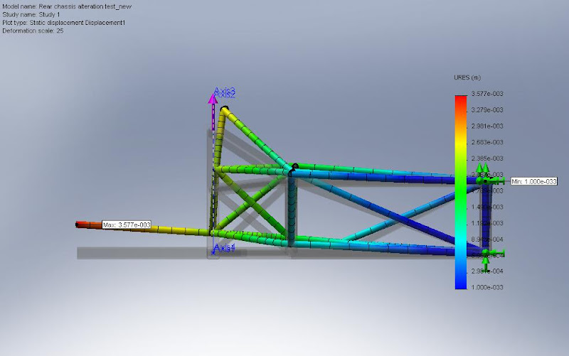
One model later and I had some more results. Same tests
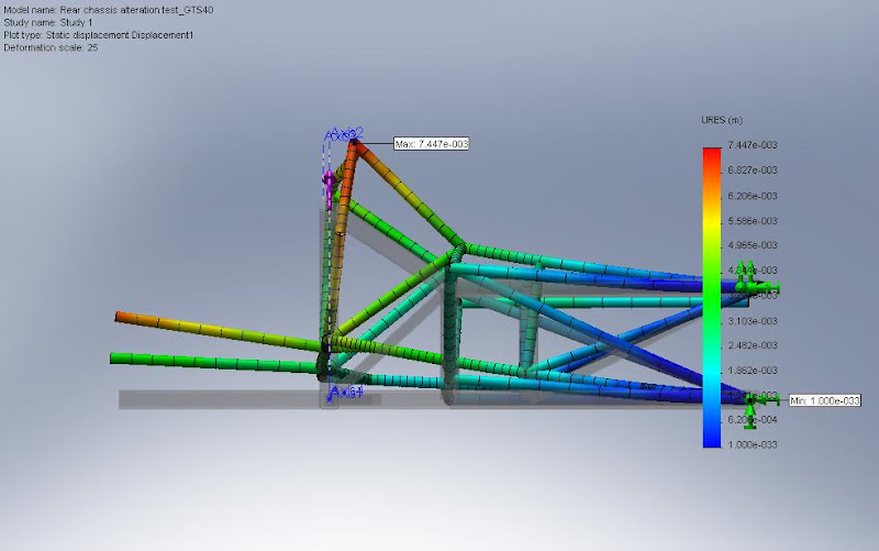
Single bump

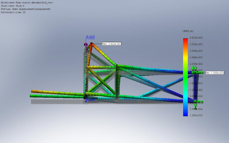

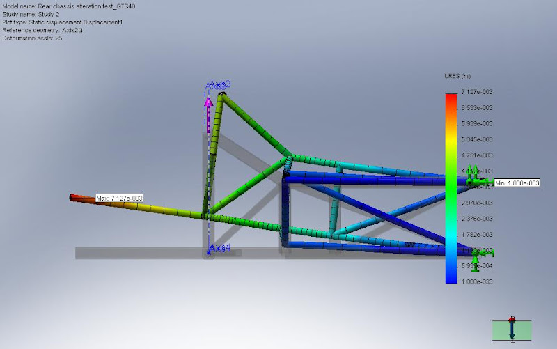
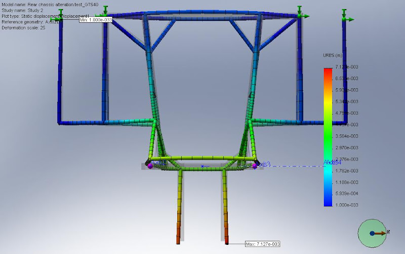
Double bump


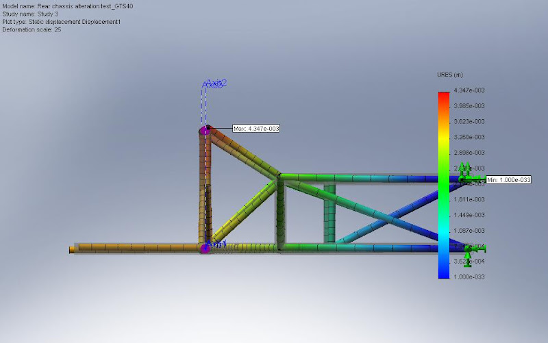
And finally side load

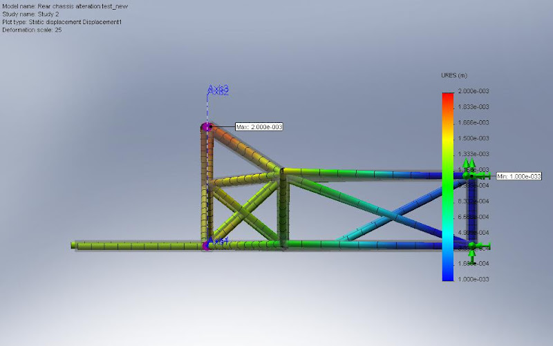
Settings are exactly the same as the initial chassis tests and despite being a very unrealistic set of tests the results are clear that the chassis is stiffer with the modifications.
Results
| Single Bump | Double Bump | Side Load | |
| Original | 7.447mm | 7.127mm | 4.347mm |
| Modified | 3.823mm | 3.577mm | 2mm |
Pretty clear improvement. Not that an improvement was the goal, it was more to ensure that by changing things I didn’t make it worse.
Onto the angle-grinder…