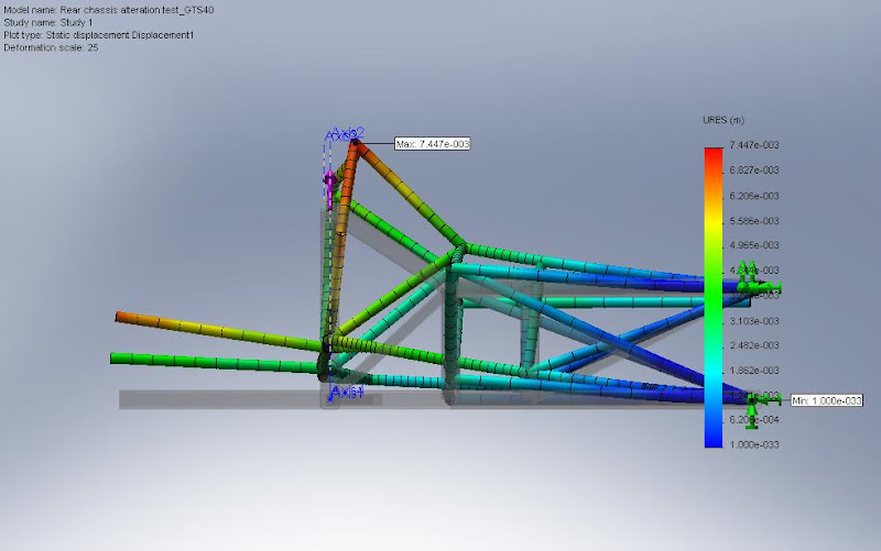
So. There I was looking at the lack of clearance between the rear-most downipe and how other manufacturers do it and then I fired up a CAD and FEA package and modelled half of the existing chassis, first off a “bump” one side (force concentrated into the shock absorber pickup):

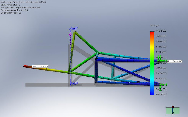
Then a “double bump”, ie both sides. (force concentrated on shock absorber mounts):

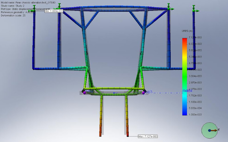
Then a side load (force split into suspension mounting points):


The displacement looks horrific but note that the deformation scale is 25x so you can “see” how it deforms. The actual maximum displacement in the first test is actually 7.4mm under a large load. I did these a long time ago now but I seem to recall I used 10000N for *each* load, that is equivalent to 1t (1000Kg). Approximately 4x the static load (assuming a car weight of 1000kg, all weight balanced evenly).