As per my previous update from 2011 I managed to pick up a CAV or SPF pedal box, it’s very very nice but unlike the originals which were cast magnesium alloy this is a fabricated steel one. It’s heavy and it doesn’t really fit.
It was substantially cheaper than an ‘after market’ pedal box, tbh it’s cheaper even than just a set of master cylinders so I didn’t feel too bad about modifying it…
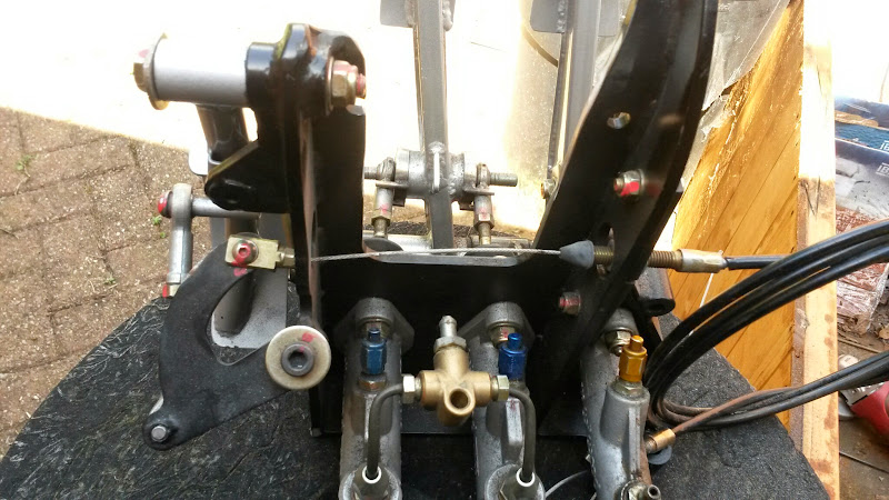
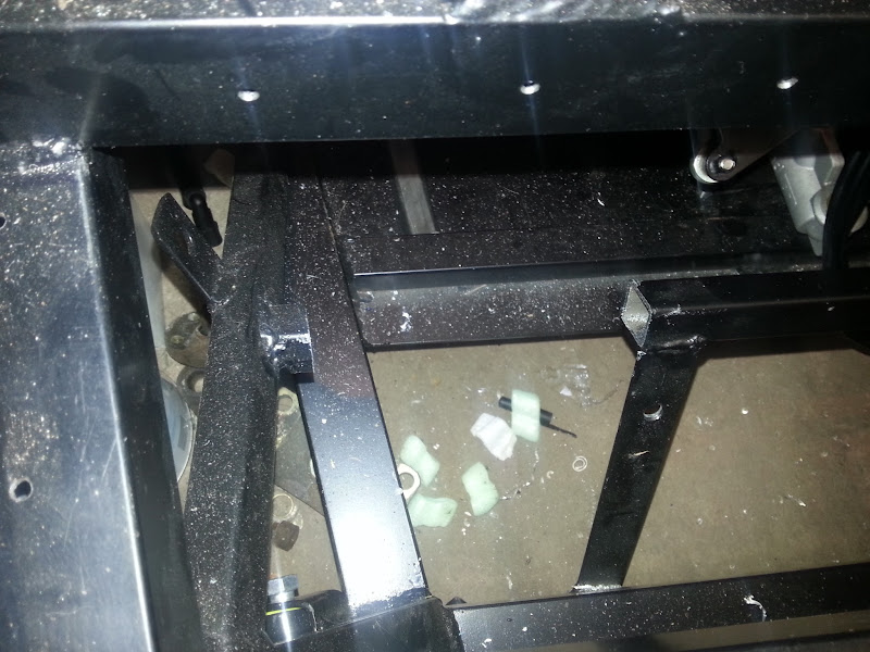
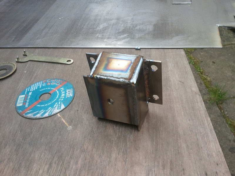
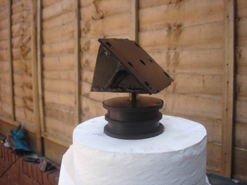
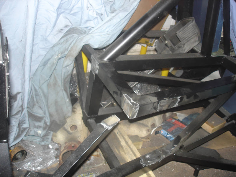
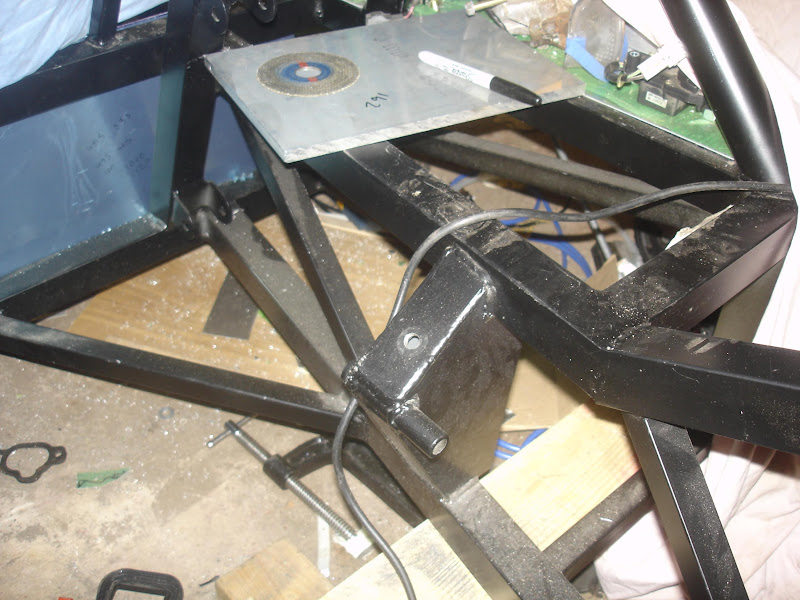
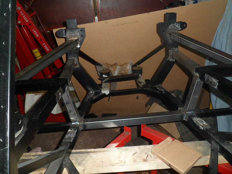
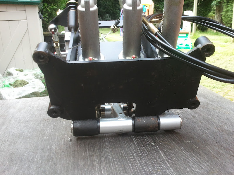
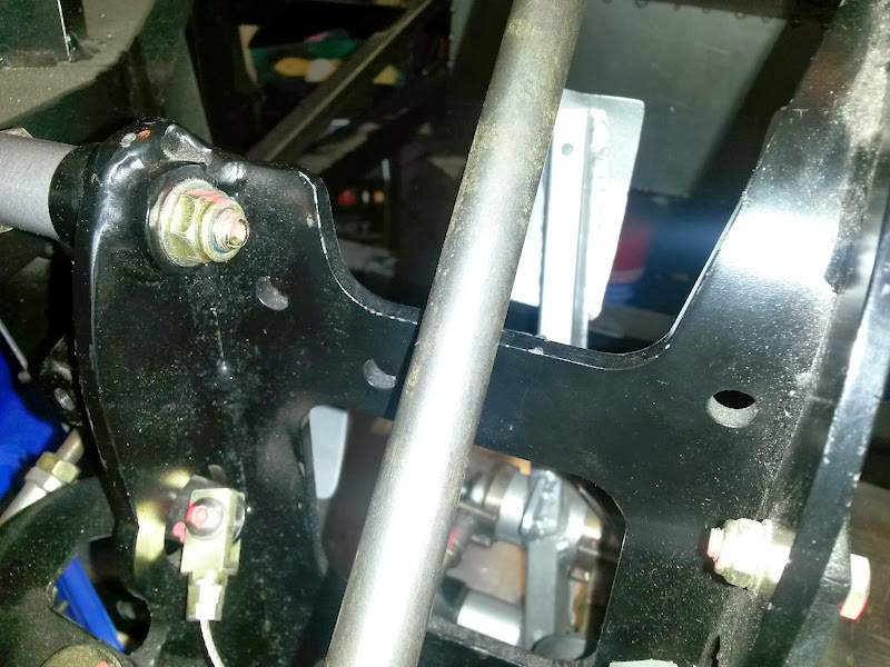
So here is the pedal box as I got it

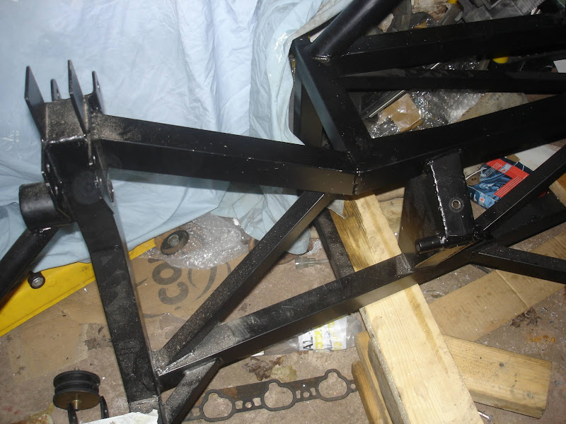
It’s very offset to the left, the throttle pedal is almost central to the steering column so the first thing was to cut the right side off so it could be moved right.
Before
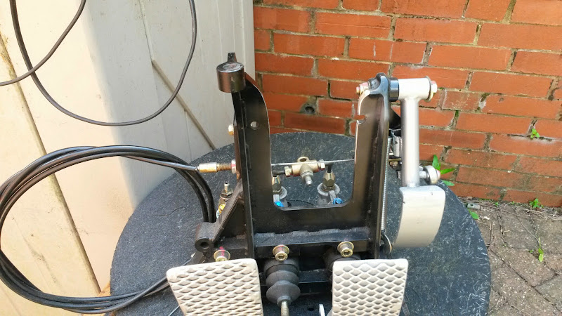
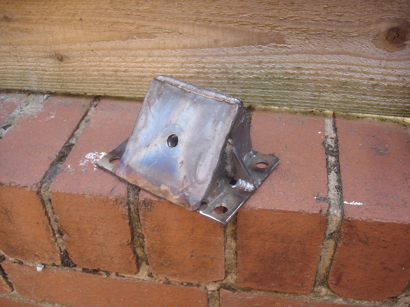
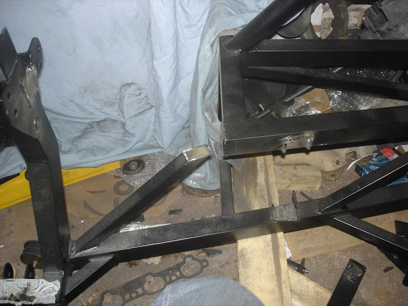
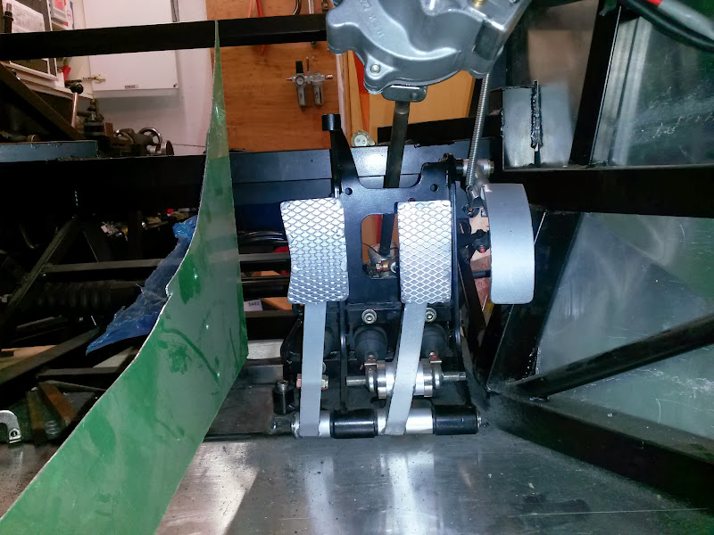
And afterwards

Much better now

So now the brake pedal is pretty much central to the steering column.
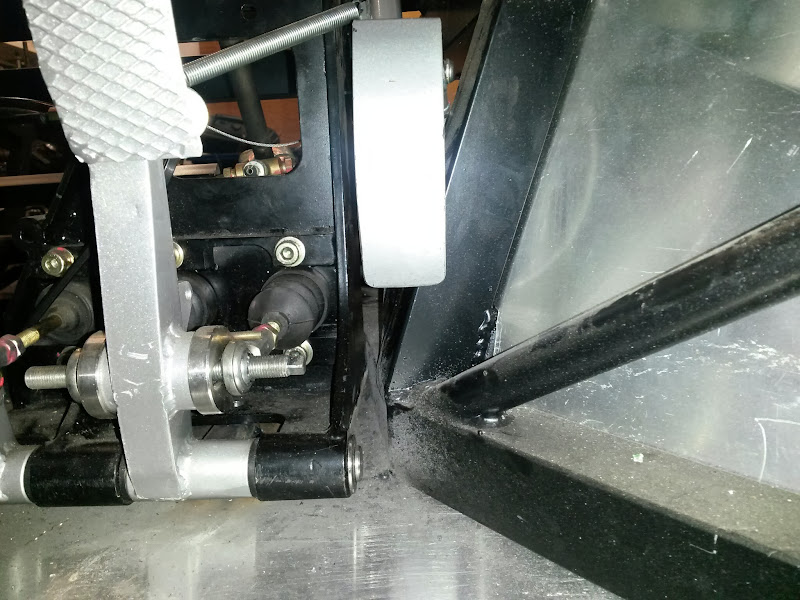
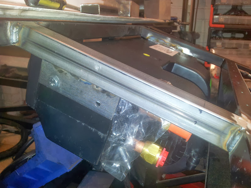
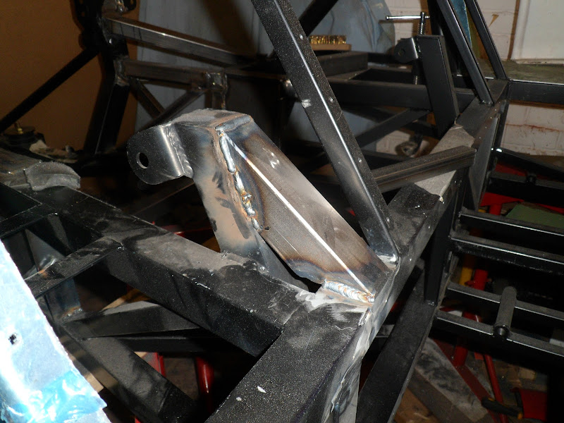
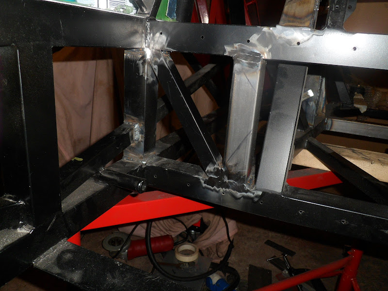
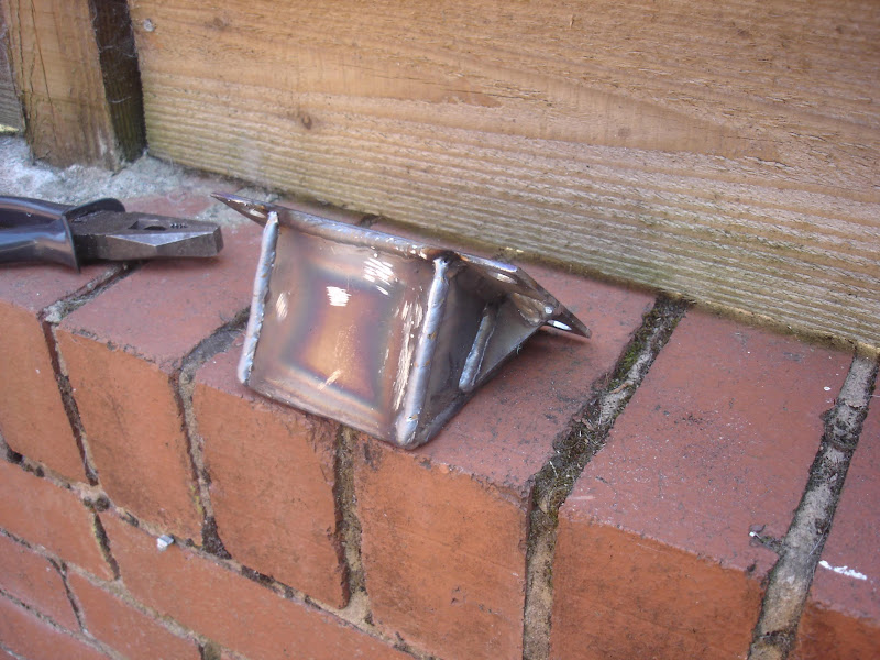
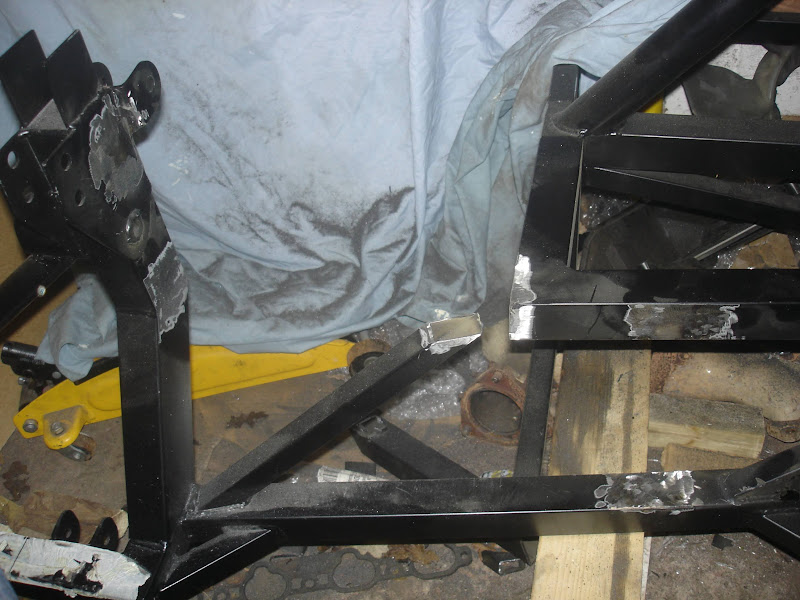
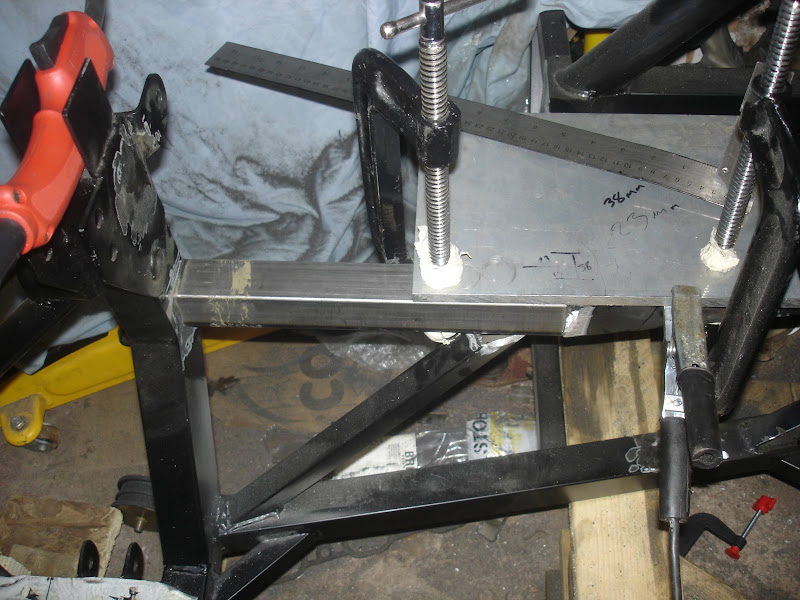
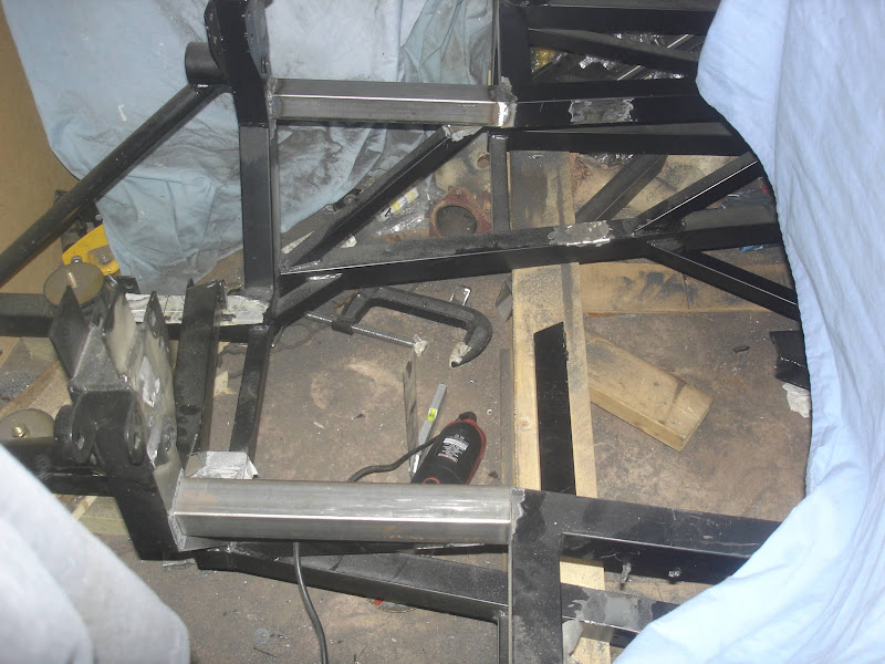
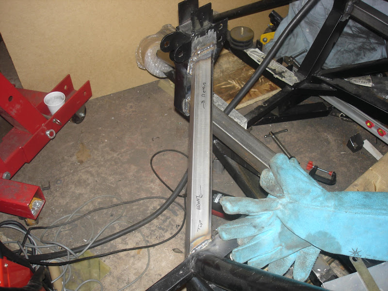
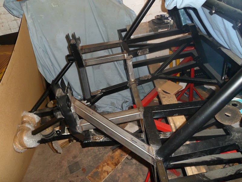
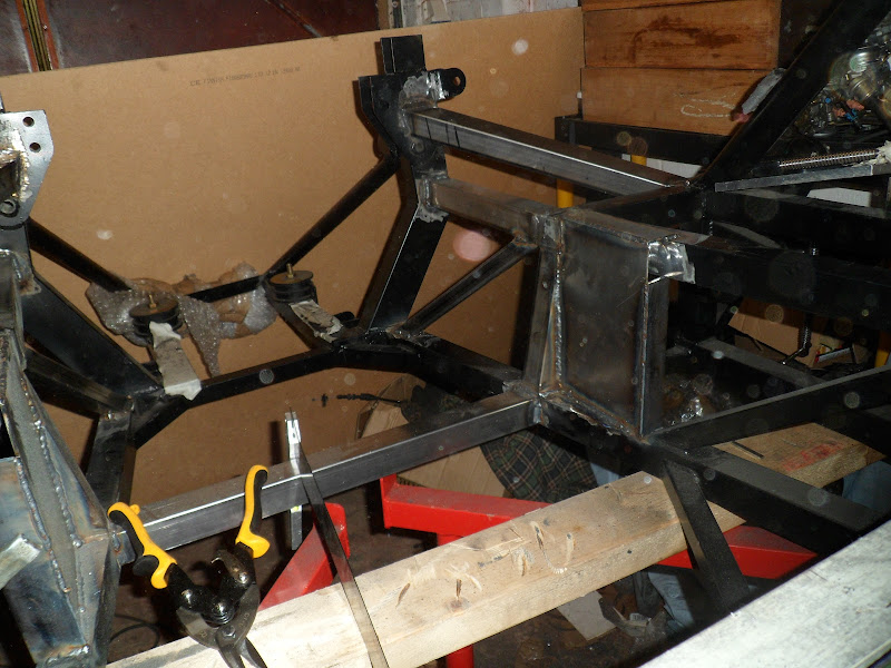
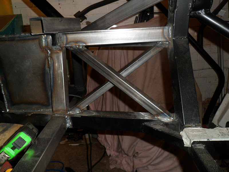
Next was how to actually mount it. I’m trying really hard to have a totally flat floor so no bolts out of the bottom of the car. The pivot for the pedals is also below the level of the base so it has to be raised up slightly. This means I had to make up two pieces like this and then weld them in (they are of course different heights).

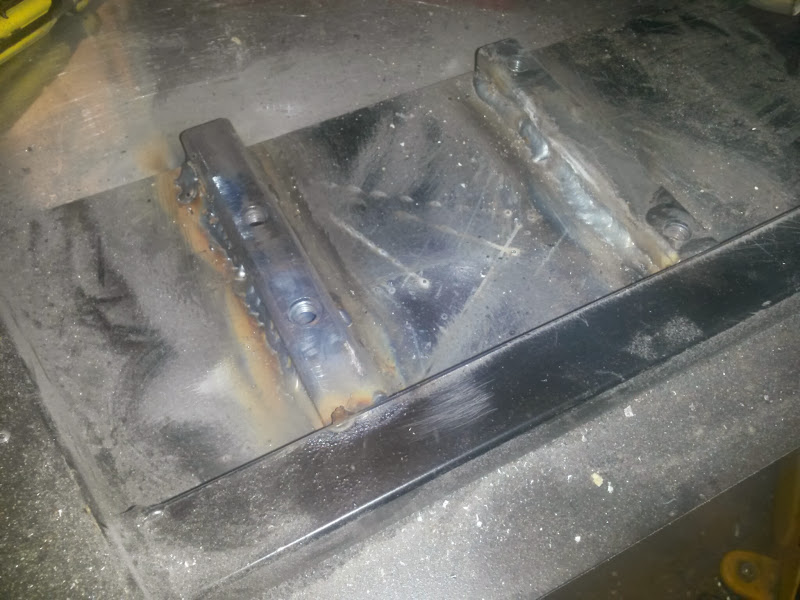
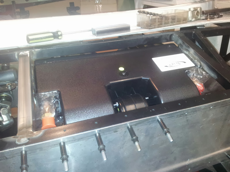
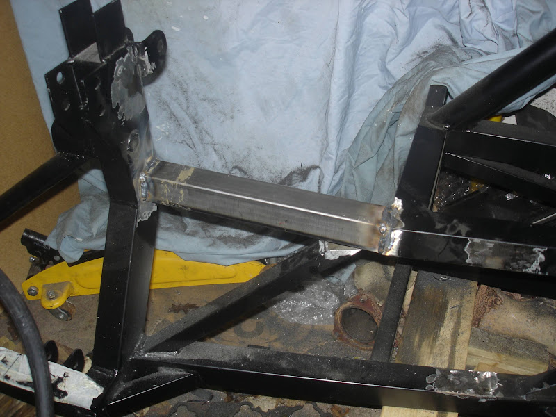
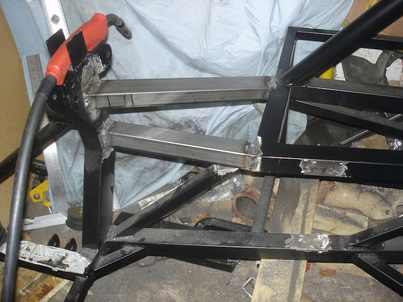
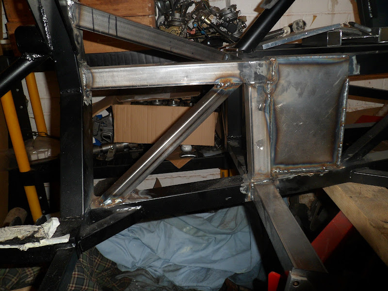
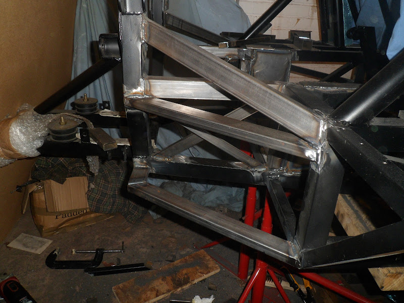
But I want to be able to properly stamp on the brakes without losing anything to the chassis flexing so welded in a brace.

It is total and utter overkill. 🙂
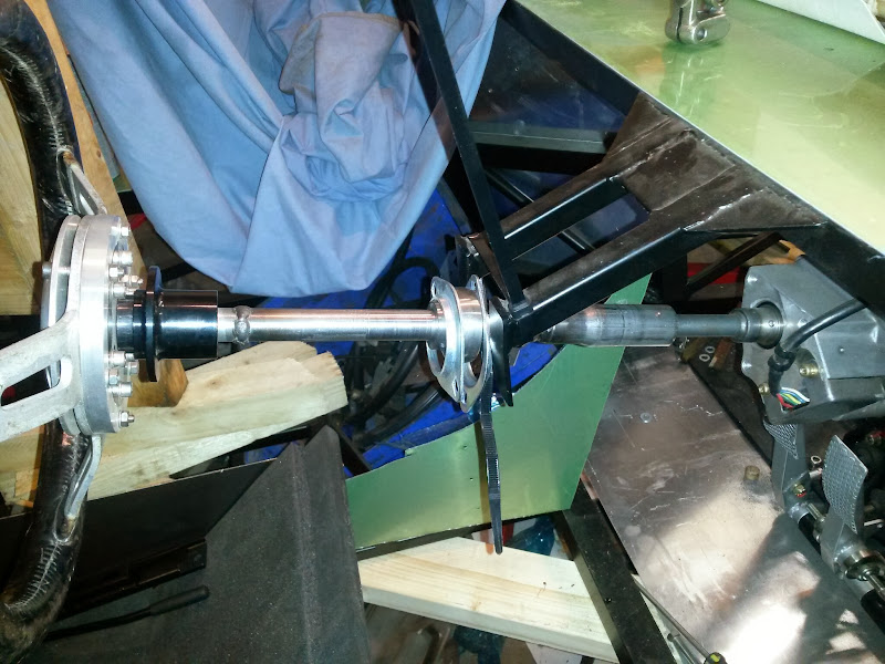
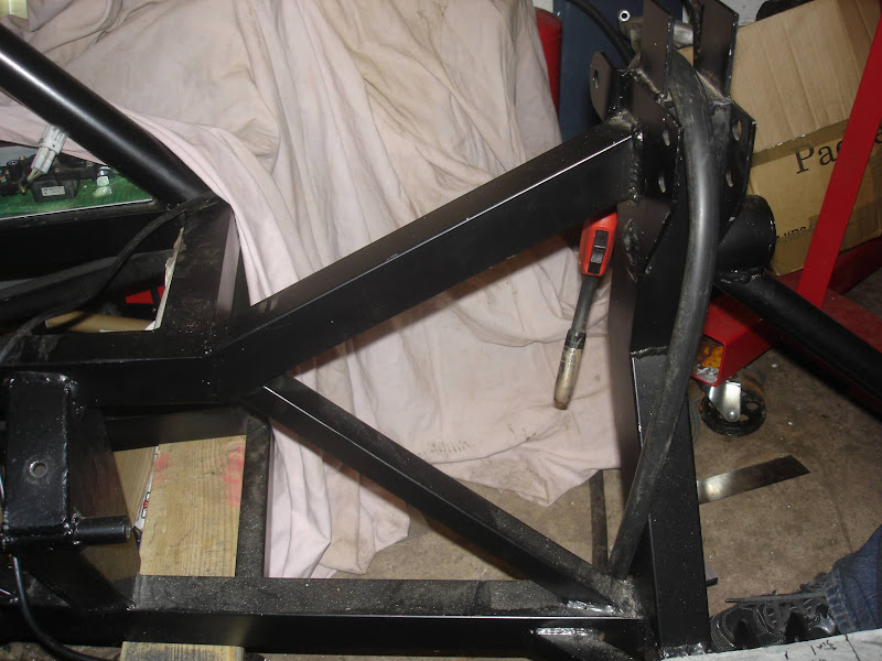
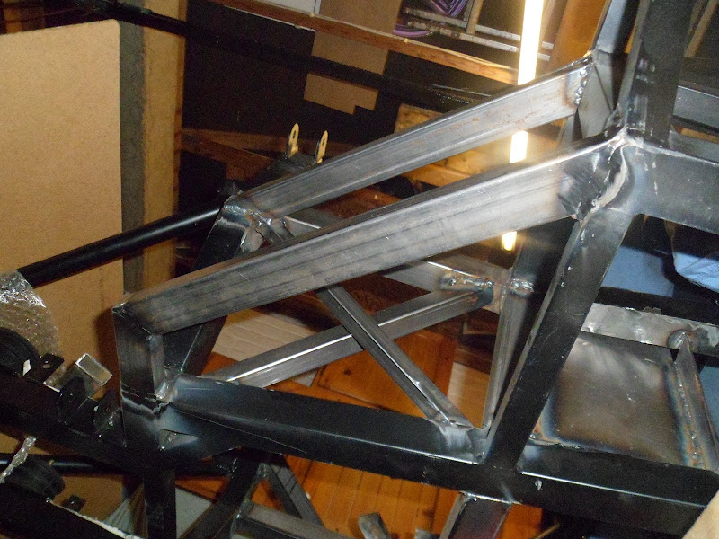
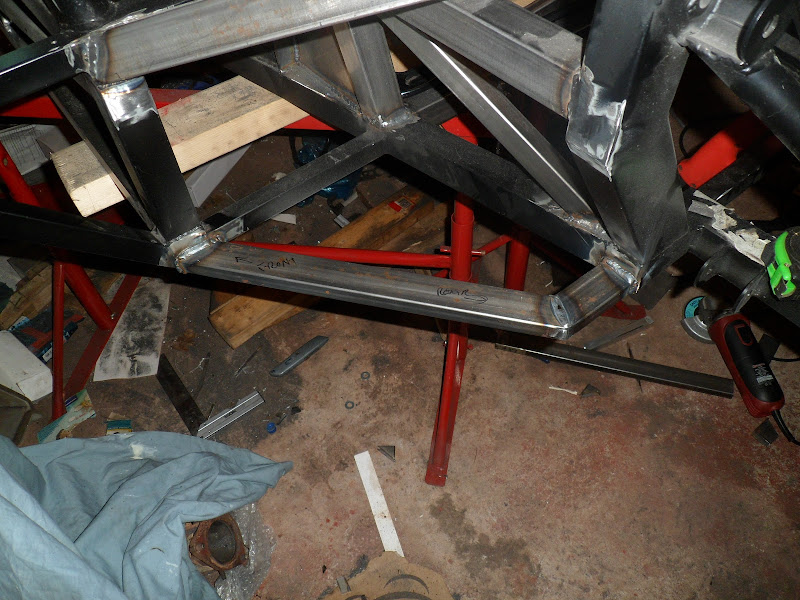
So now that the pedal box is very firmly attached time to look at the drop link again
Hmmm, solution looks pretty easy to me…